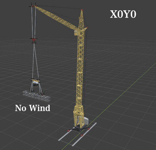
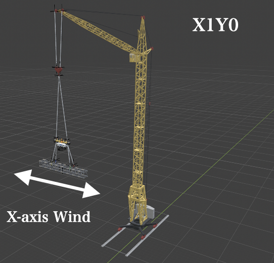
Payload Control Environment
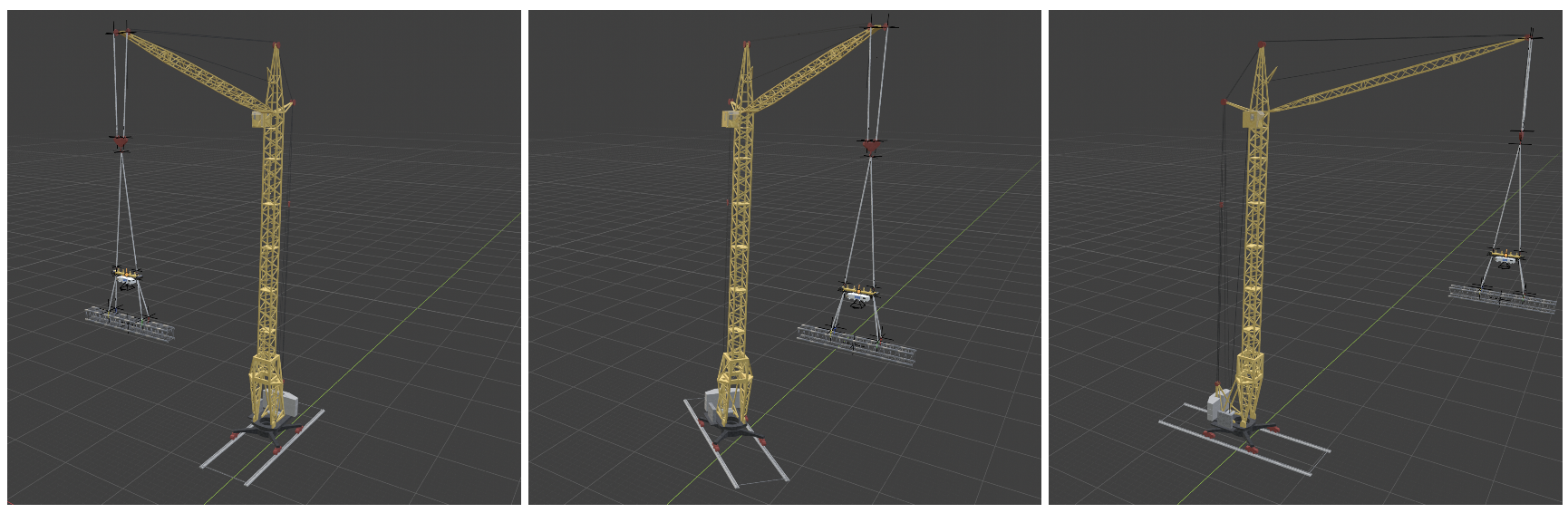
A simulation environment was developed to control the payload yaw angle. The environment includes a crane, controller, payload, suspension ropes, and wind disturbances.
Control Objective
The objective is to rotate the payload to the target yaw angle of 90° within a control period of approximately 60 seconds.
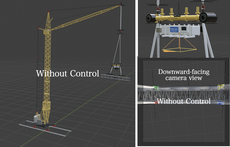
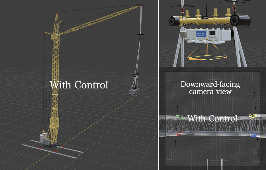
Crane Rotation
The crane rotates by 90° over approximately 55 seconds and then remains stationary until the end of the 60-second simulation. During crane rotation, the controller continuously regulates the payload toward the target yaw angle.
Payloads
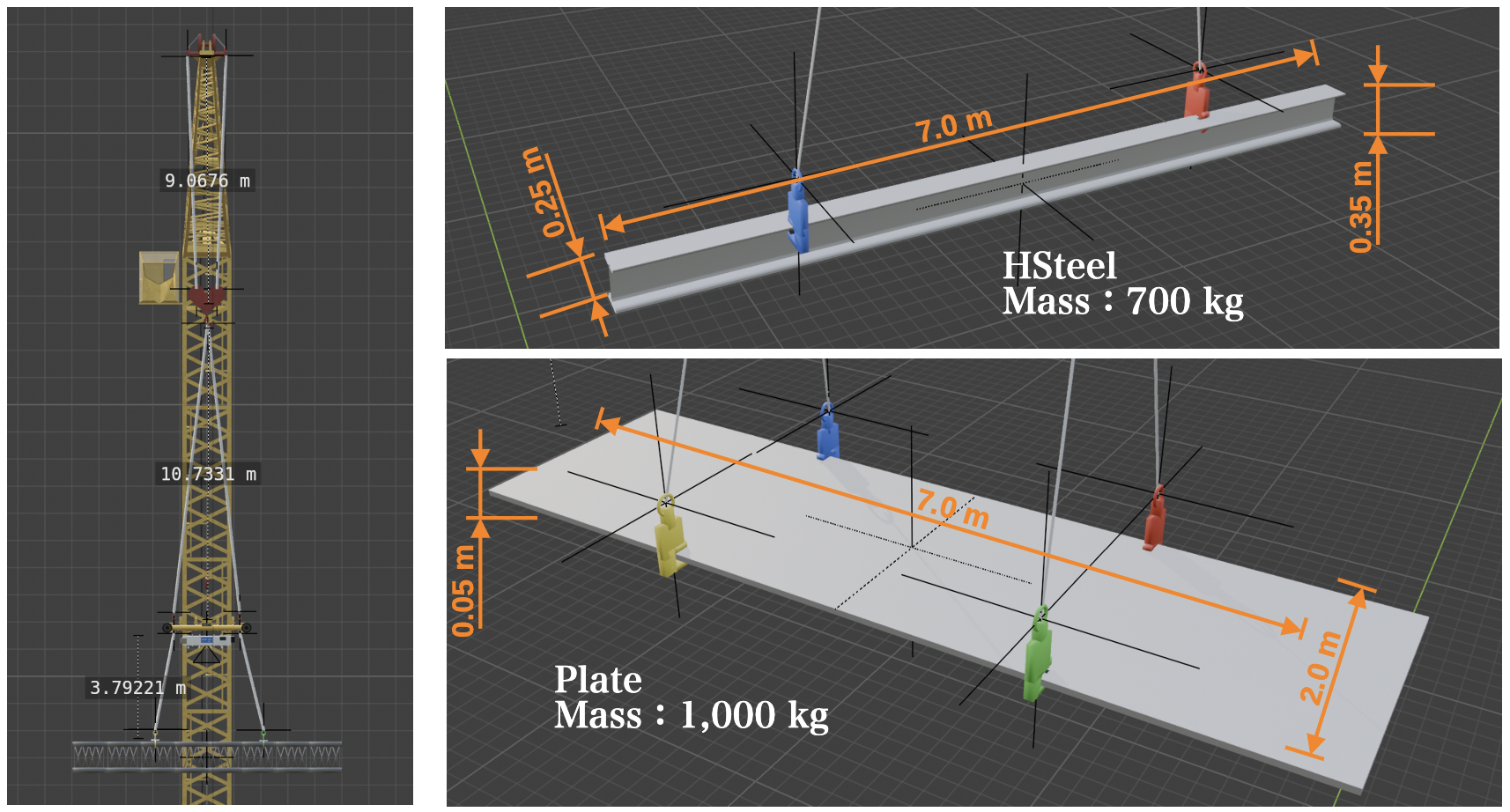
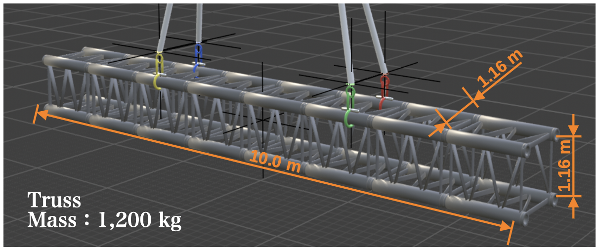
Payloads with two-point and four-point suspension configurations are used to evaluate whether the same control method can be applied to payloads with different shapes and inertial properties.
Controller
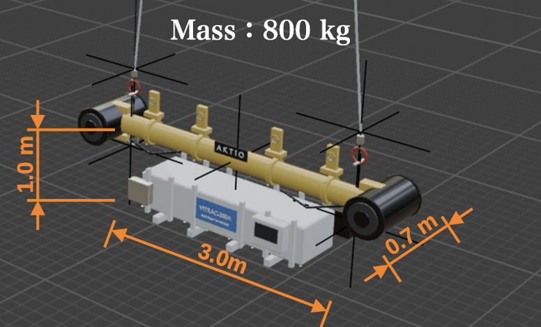
A controller equipped with four thrusters is mounted above the payload. By combining the thrust generated by each thruster, the controller produces clockwise or counterclockwise yaw moments to regulate the payload orientation.
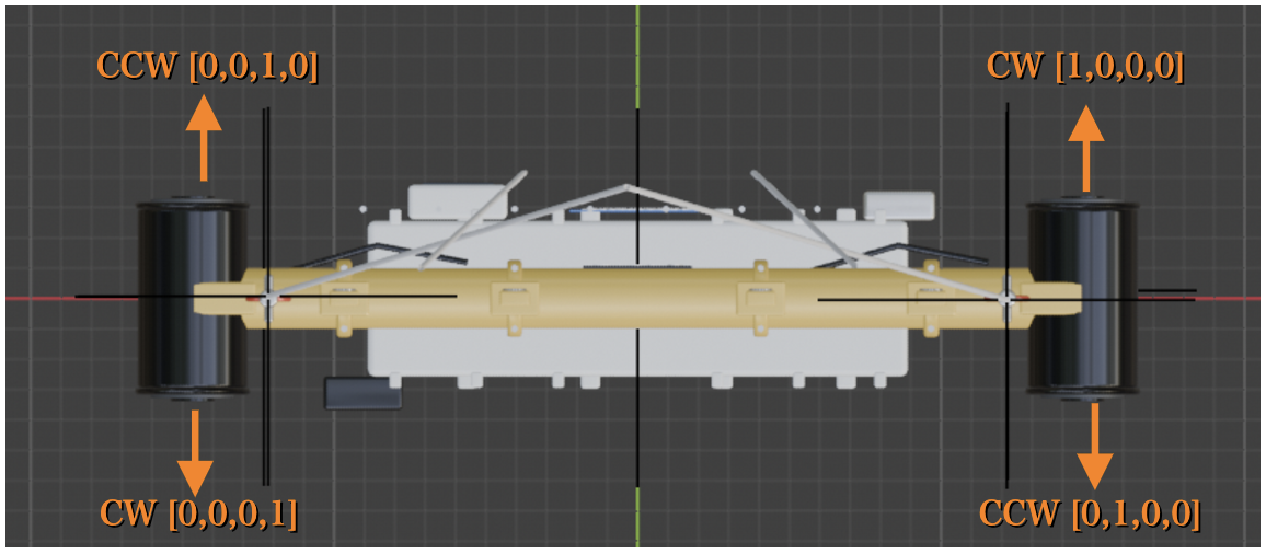
- Thrusters
- 4
- Maximum Thrust
- 250 N per thruster
- Output Range
- Normalized value (0.0–1.0)
Thruster Output and Payload Yaw
The following demonstration activates one thruster at a time at its maximum output (250 N). Diagonally opposite thrusters generate yaw moments in the same rotational direction. During control, the reinforcement learning model combines the outputs of all four thrusters to rotate the payload toward the target yaw angle.
The Japanese labels in the video indicate the resulting yaw direction: clockwise or counterclockwise. The values in brackets represent the normalized output vector of the four thrusters.
Control Frequency
The control model updates the outputs of the four thrusters at 3 Hz (approximately every 333 ms). Since the simulation runs at 30 fps, each computed output is held for approximately 10 frames before the next control update.
The actual thrust is calculated by multiplying the normalized output (0.0–1.0) by the maximum thrust of each thruster.
Disturbance Conditions
Three disturbance conditions are used to evaluate the control performance: no wind, a constant wind in the X direction, and a circular wind disturbance whose direction changes over time. The disturbance conditions become progressively more challenging, allowing the robustness of the controller to be evaluated.