Yaw Estimation
A payload yaw estimation model was developed and evaluated for use in the control system, where the estimated payload yaw angle is obtained from images.
Workflow
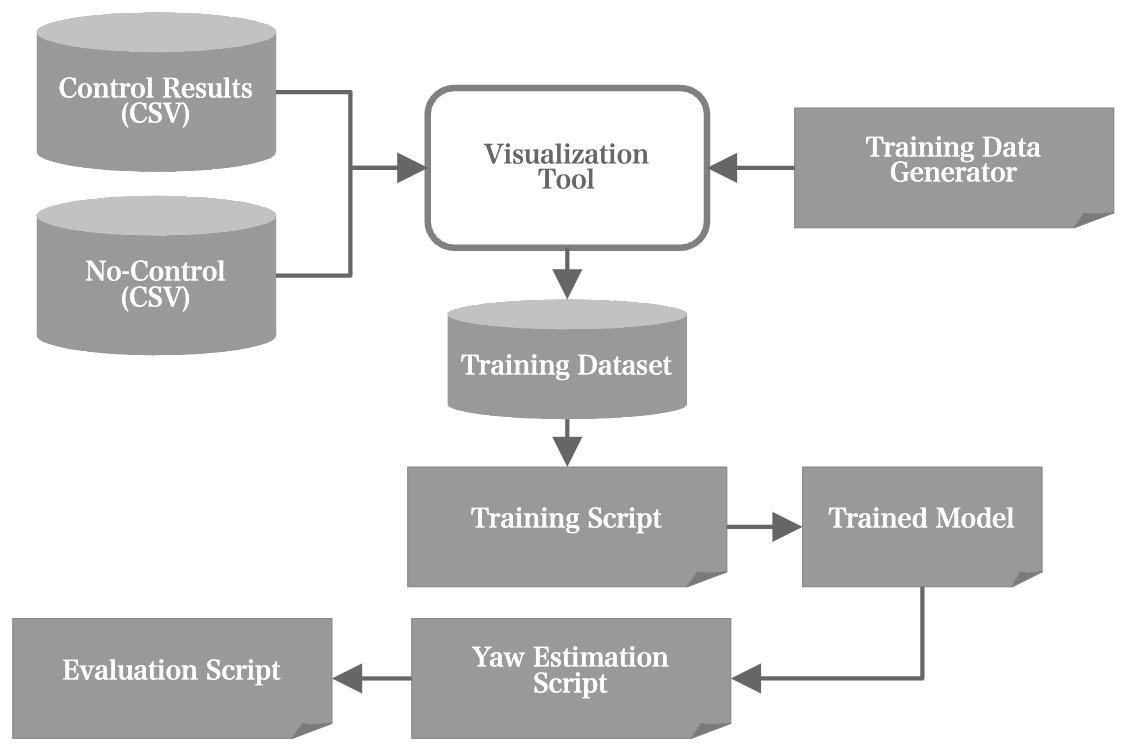
Training data were generated from the control evaluation results (CSV files) and used to train the payload yaw estimation model.
Training Data
Training images were generated from the downward-facing camera mounted on the controller. Three payload types were captured under various disturbance conditions, and the hook positions were used as the ground truth.
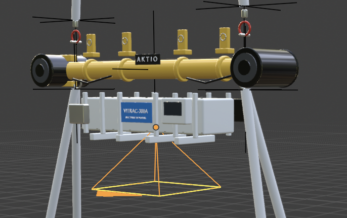
The training dataset was created from images captured by the downward-facing camera mounted on the controller.
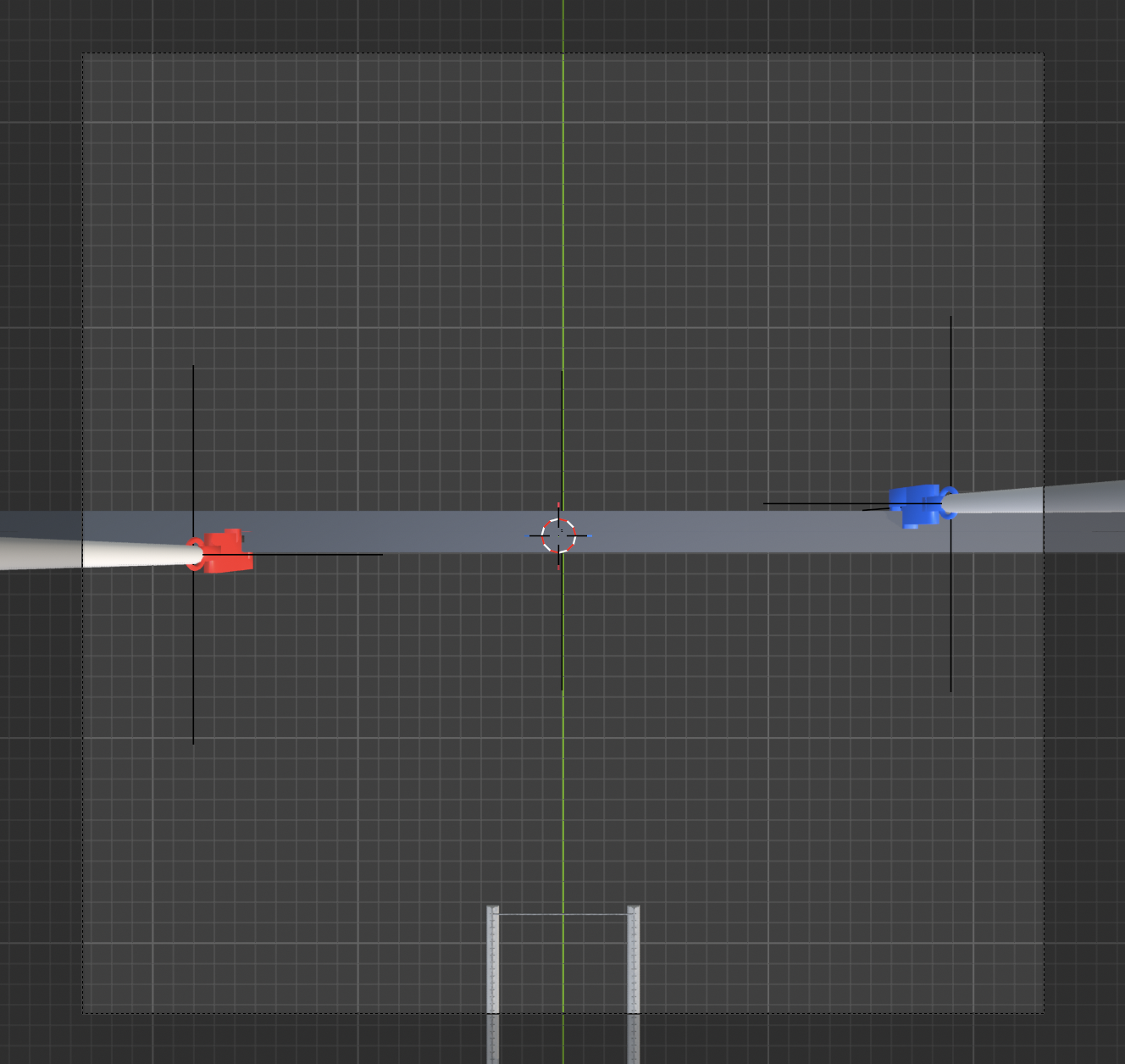
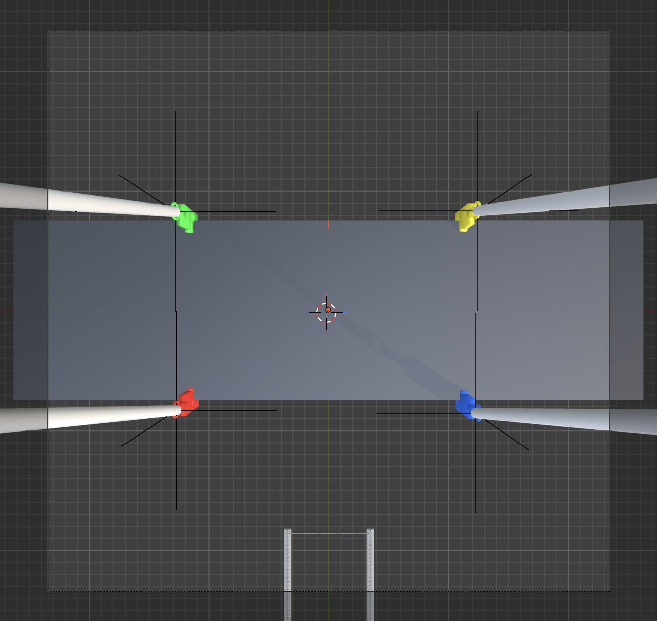
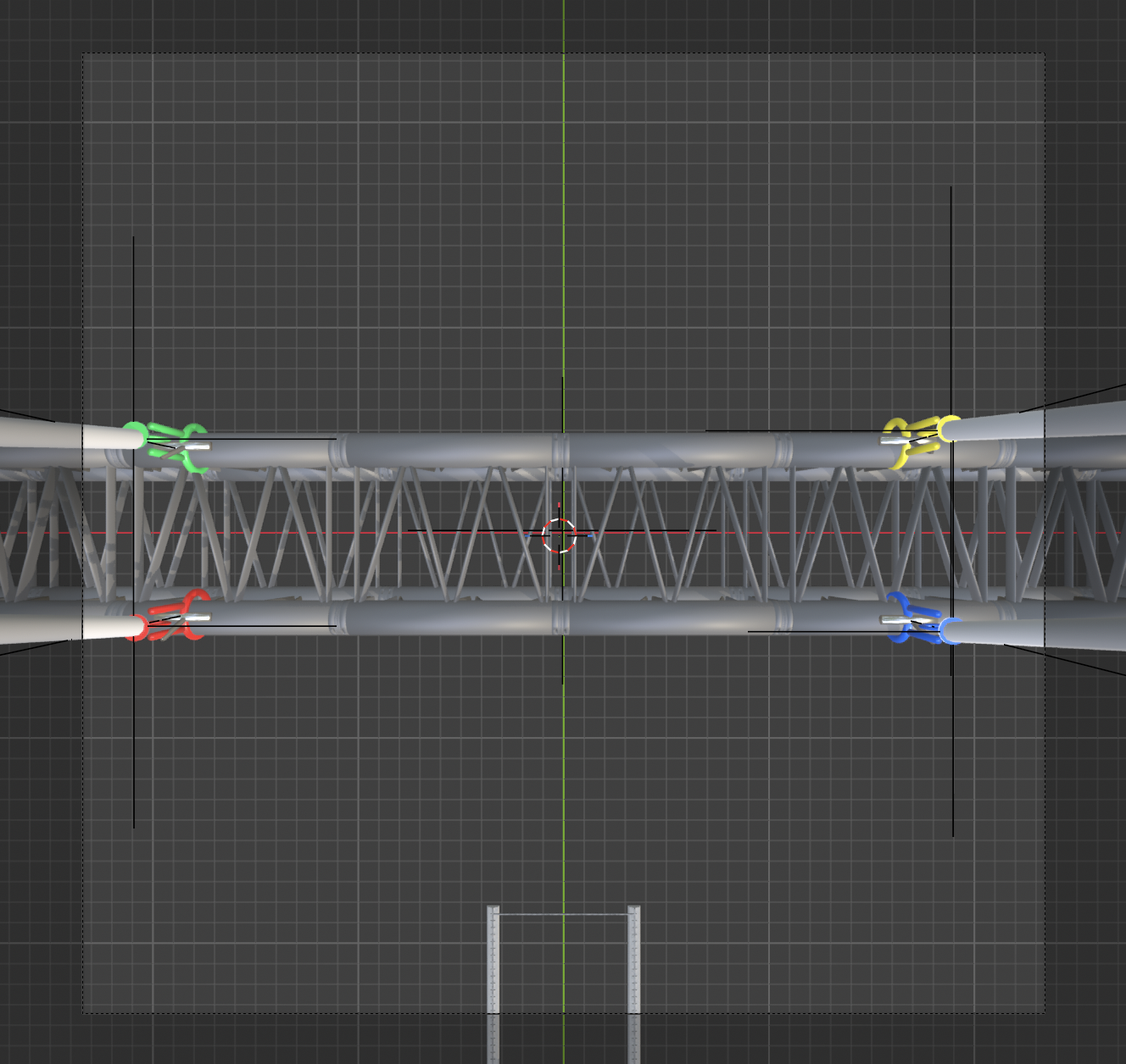
Training was performed using two datasets, Baseline and Auto, generated under different conditions.
Detection Targets
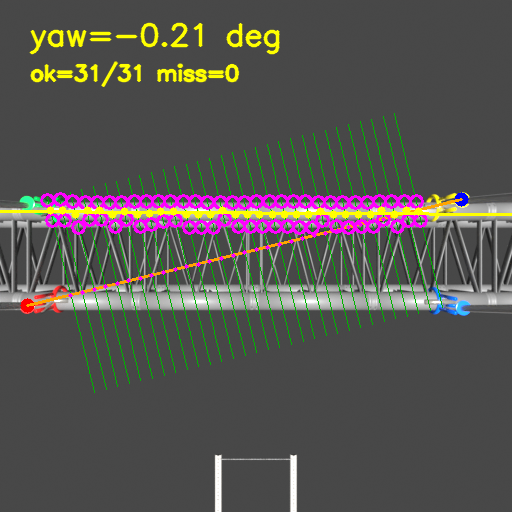
The hooks of the HSteel, Plate, and Truss payloads are detected, and the payload yaw angle is calculated from the estimated hook positions.
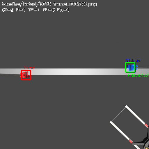
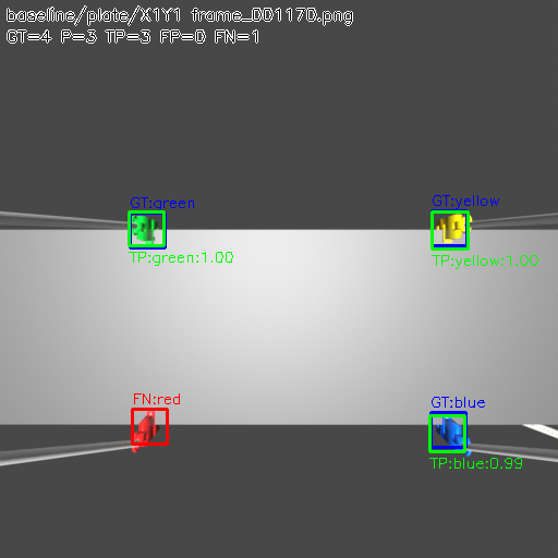
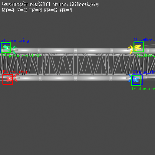
Yaw Estimation
The trained model detects the hook positions, and the payload yaw angle is calculated from the detected hook positions. Even when some hooks are not detected, the yaw angle can still be estimated from the remaining detections.
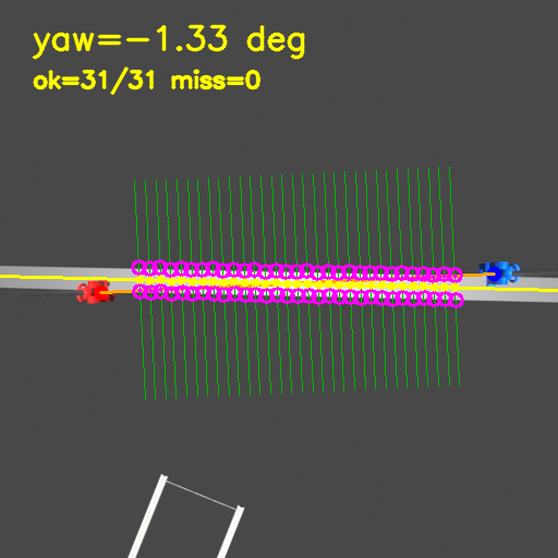
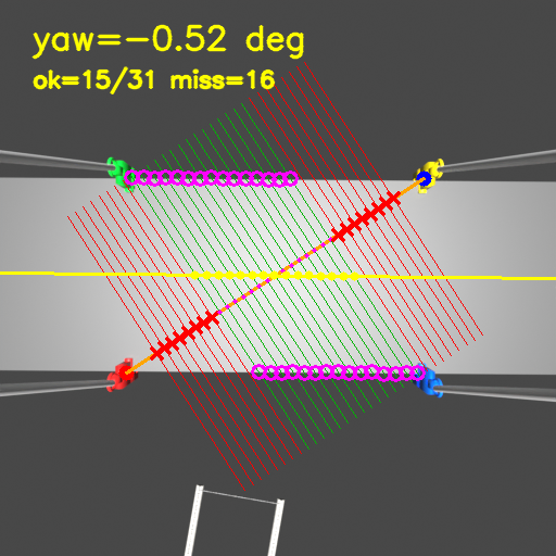
Accuracy Evaluation
The estimated yaw angle was compared with the ground truth to evaluate estimation accuracy.
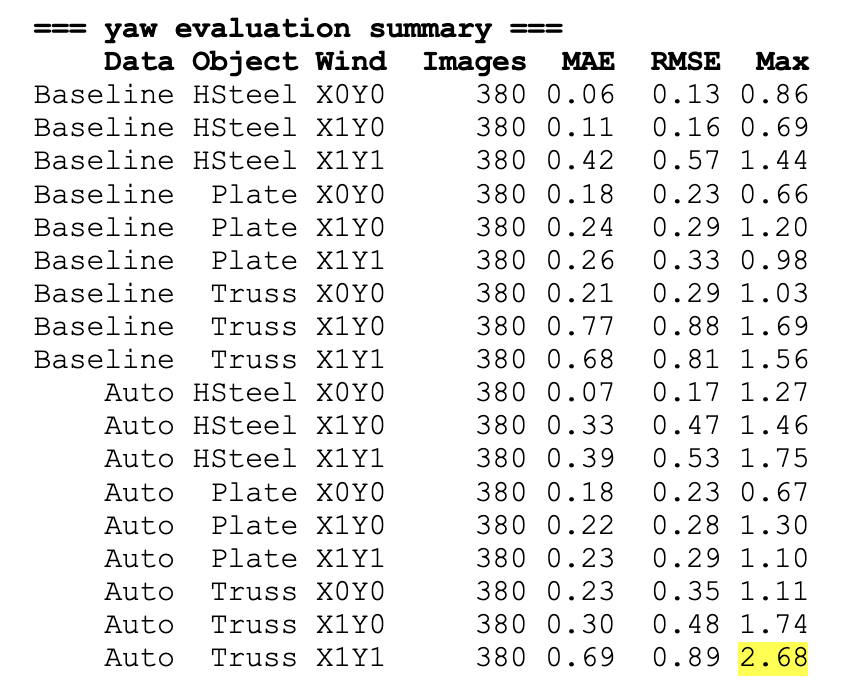
For the HSteel and Plate payloads, the MAE remained below approximately 0.4° even with the Auto dataset, demonstrating high estimation accuracy.
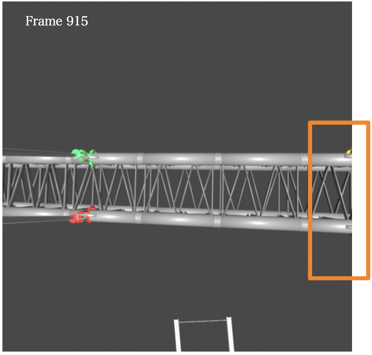
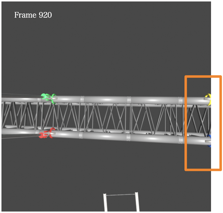
The largest error (2.68°) was observed for the Truss payload under the X1Y1 disturbance condition, which was also the most challenging case in the control evaluation. See Largest Error for details.
- Data: Baseline vs. Auto
- Object: HSteel / Plate / Truss
- Wind: X0Y0 / X1Y0 / X1Y1
- Images: Number of evaluation images
- MAE: Mean Absolute Error
- RMSE: Root Mean Square Error
Unit: degree
Baseline vs Auto
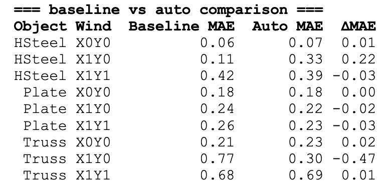
The estimation accuracy was compared between the Baseline and Auto datasets.
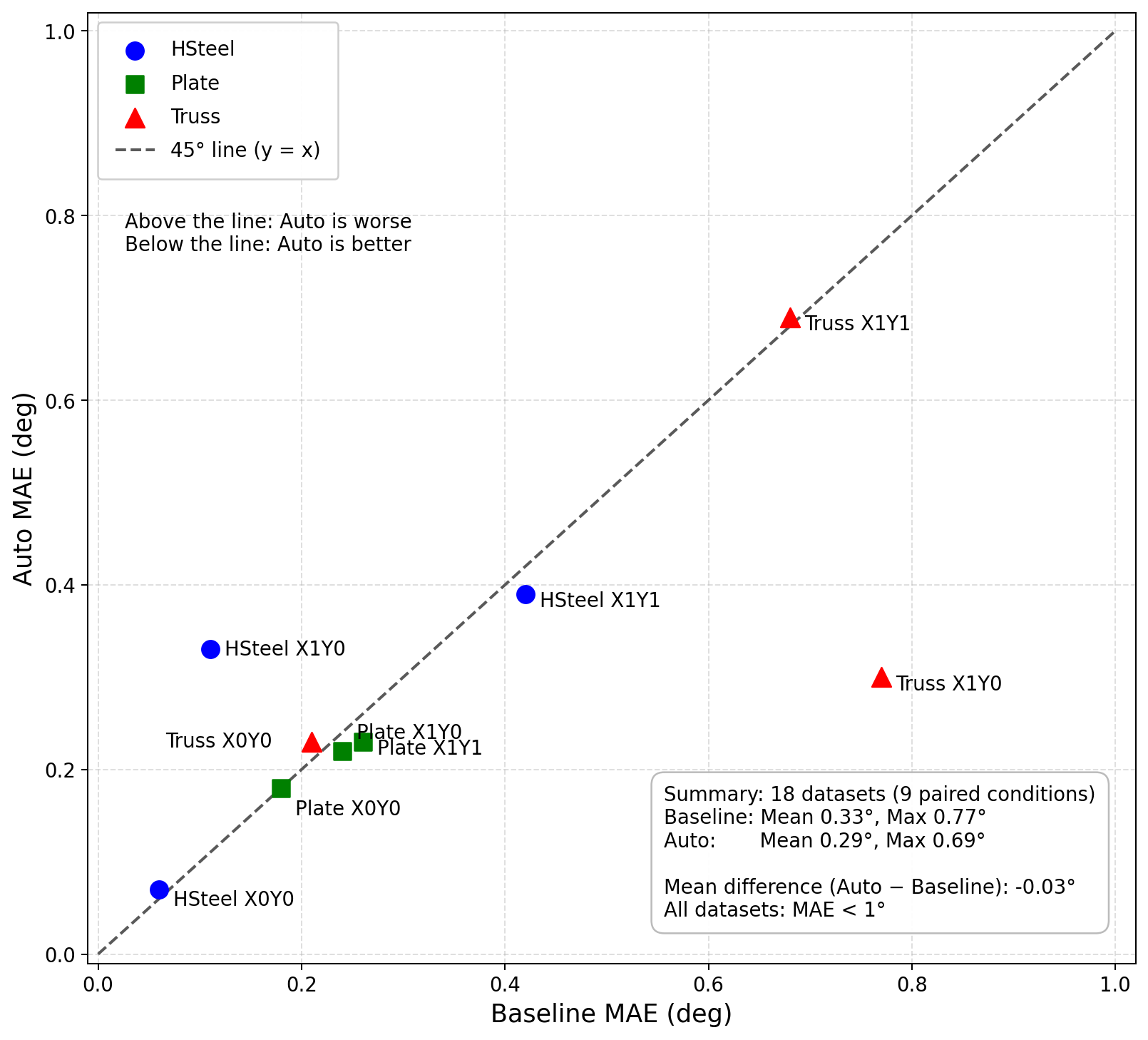
Most results are distributed close to the 45° line, indicating that the estimation accuracy is nearly identical for the Baseline and Auto datasets. Although the differences appear noticeable in the plot, the absolute errors are all below 1°, demonstrating equivalent estimation performance in practice.
Largest Error
The causes of the largest estimation errors were investigated.
The largest estimation errors occurred for the Truss payload, where some hooks moved outside the camera view and could not be detected. Even in these cases, temporal processing compensated for the missing detections, so the impact on the control performance was limited.
A slight impact was observed only during execution on the Raspberry Pi.